BBB-EXP7H
Version 2.0
BeagleBone Black 7 Inch LCD Expansion board (Abbreviate as BBB-EXP7H) designed by Chipsee. It has two versions: Capacitive Touch Version and Resistive Touch Version.
Hardware Features
BBB-EXP7H |
|
|---|---|
Display |
7 Inch LCD, 1024*600 Pixel, 250nit Brightness by default (400 nit optional) |
Touch |
Five Point Capacitive touch, Covered with Amorplate Glass (Or Reisistive Touch); |
Audio |
On board Speaker(1W), 1 Audio out, 1 Mic In Connector (Can change to Line in by changing resistor) |
RTC |
Use Battery CR1220, Not Mounted by default. |
RS232 |
2 Channels, COM0 and COM1 |
RS485 |
2 Channels, COM2 and COM4 |
CAN |
1 Channel, CAN0 |
Buzzer |
1 |
KEY |
5 User defined keys, 1 Reset Key, 1 Power Key |
LED |
2 User defined LEDs |
Sensor |
Three-Axis Digital Accelerometer |
Power |
5V, 3W power Consumption |
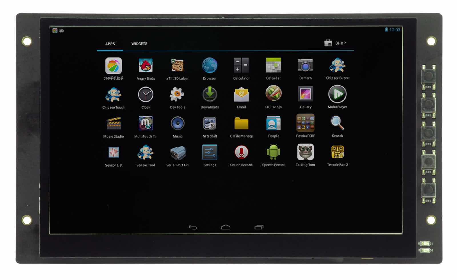
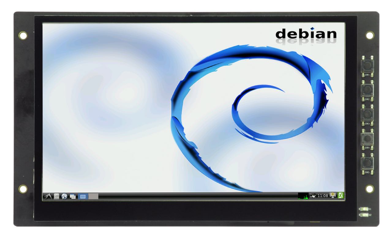
Figure 1 BBB-EXP7H (Capacitive,Android 4.2)
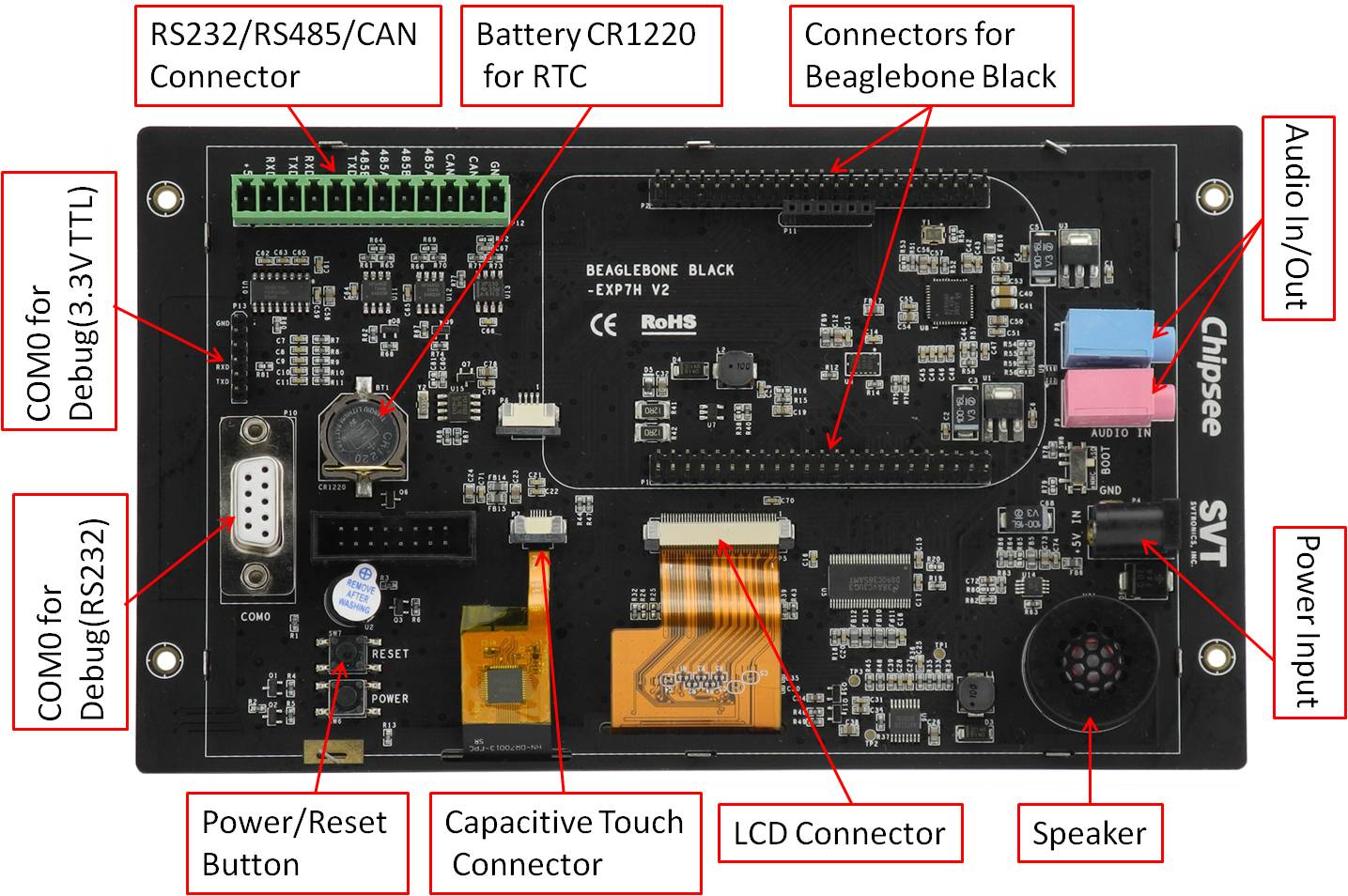
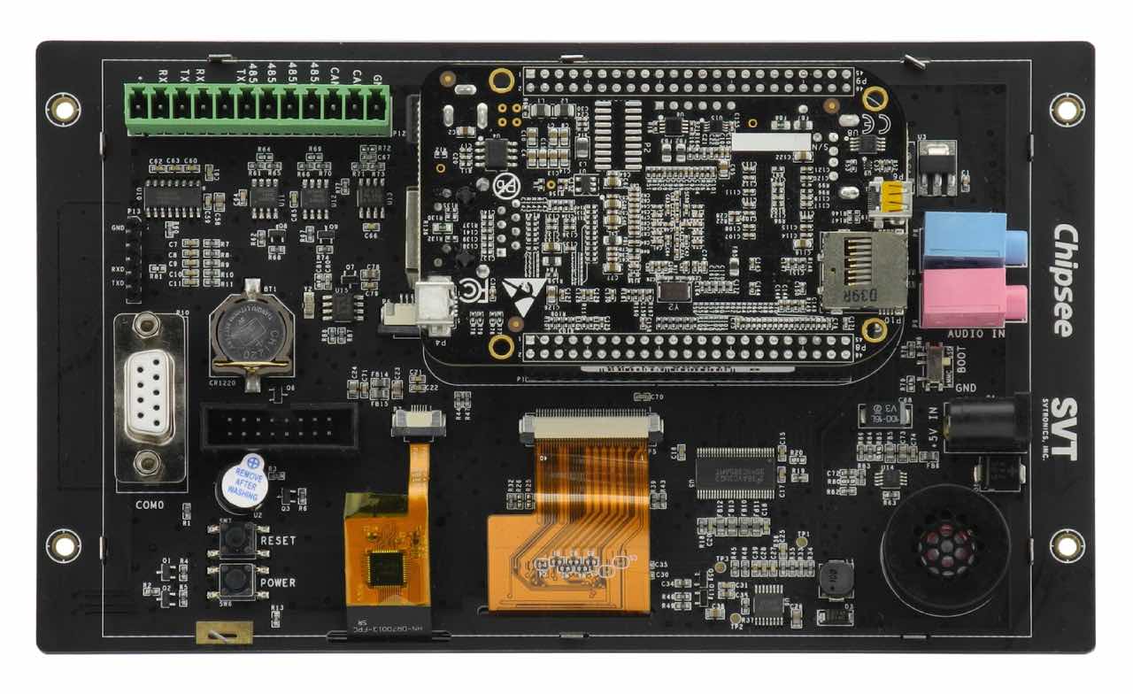
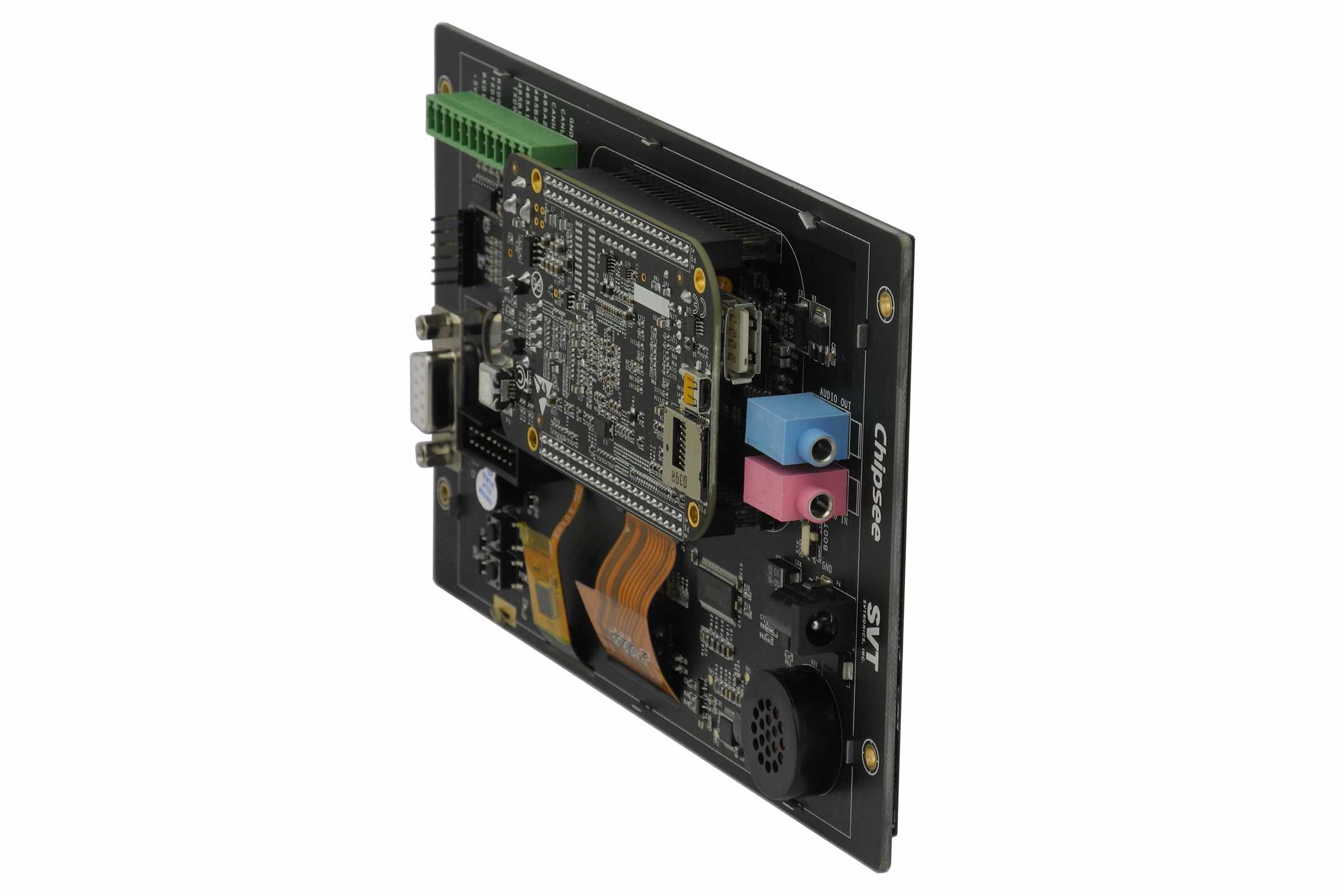
Figure 2 BBB-EXP7H Back-Side View (Capacitive)
How to connect BBB-EXP7H with BeagleBone Black
When connect BBB-EXP7H with BeagleBone Black, Figure 3 shows the right connects direction. If connect on the wrong direction, the Beaglebone Black can’t be push down to connect tightly: The LAN connector on Beaglebone Black will conflict with the Audio connector on the BBB-EXP7H.
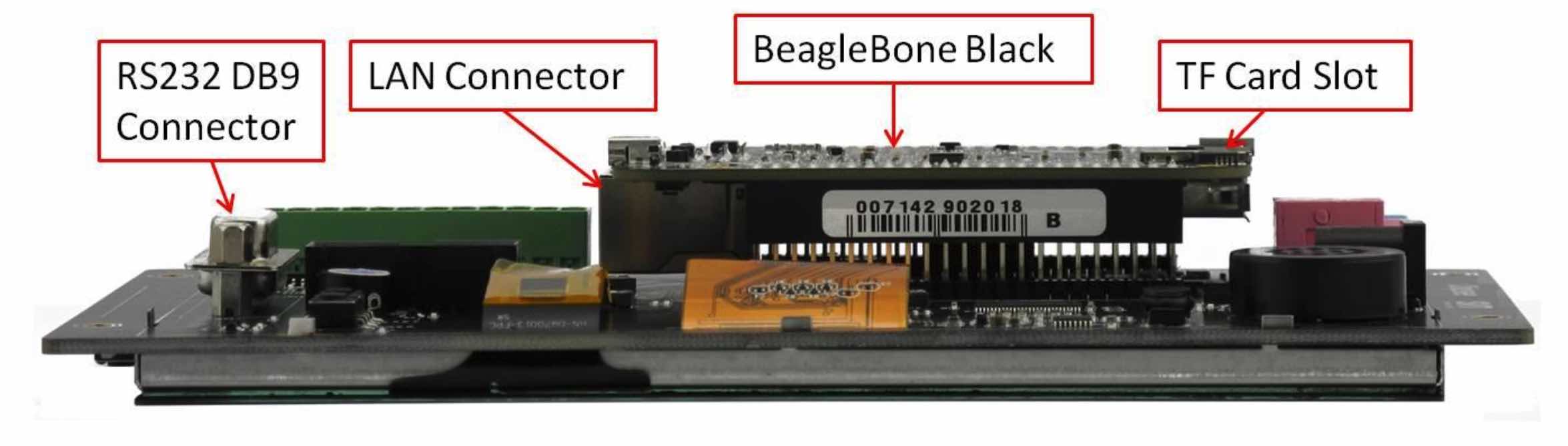
Figure 3
How to connect Power to the System
BeagleBone Black use 5V DC power Input, BBB-EXP7H use 5V DC power also.
When BBB-EXP7H connect with BeagleBone Black, the Power connector on BeagleBone black will be hide by the RS485 connector. User can provide 5V power to the power connector on the BBB-EXP7H connector P4 ONLY as Figure 4 shows. This 5V power will be connect to Beaglebone Black. 5V/2A power adapter will be necessary.
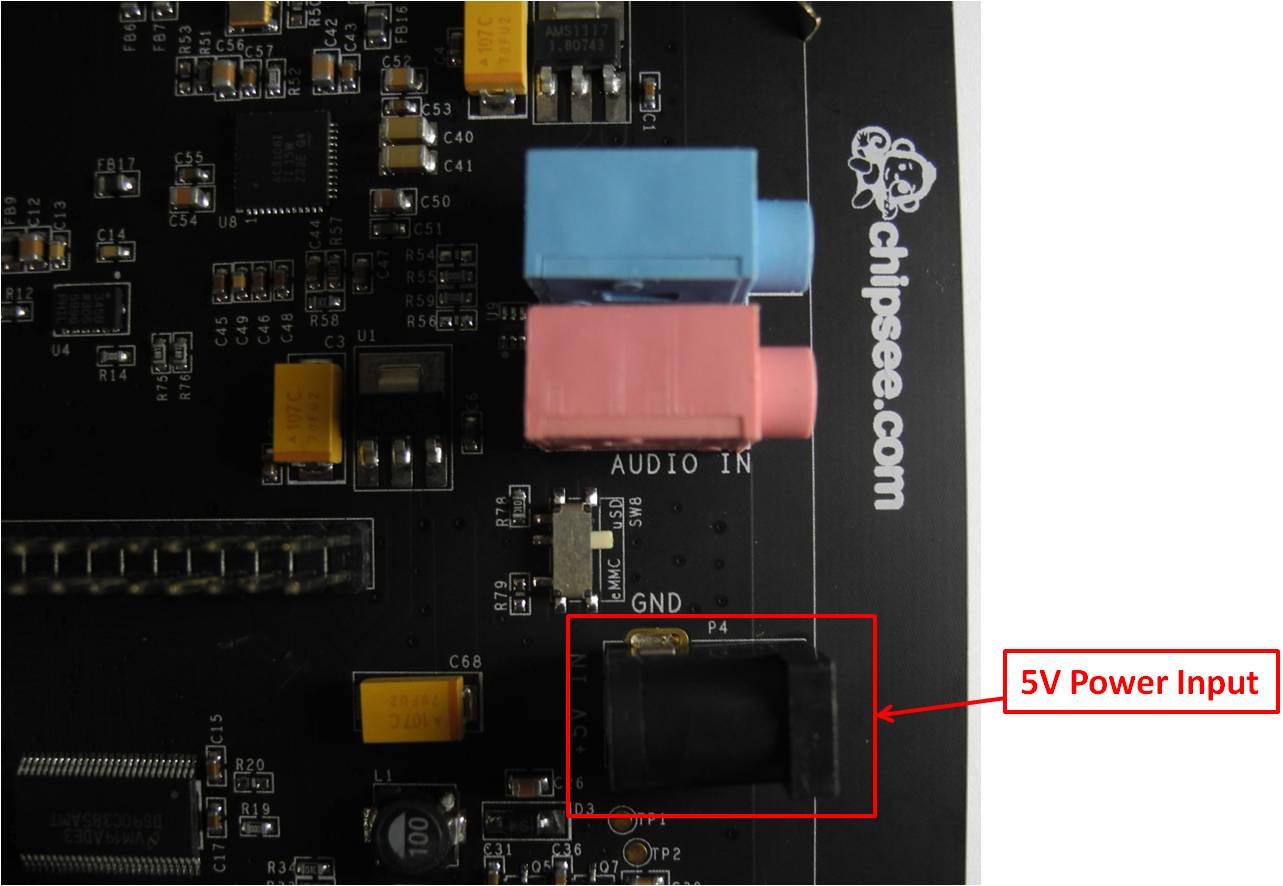
Figure 4
How to change Boot Method
Beaglebone Black can be changed boot method by push the Button S2: Push button S2 when system power on, BeagleBone Black will boot from uSD card, or it will boot from eMMC by default.
When connect with BBB-EXP7H, the Button S2 on the Beaglebone black will be hide and not easy to touch. BBB-EXP7H connect this boot signal to switch SW8 as Figure 5 shows. When user switch it to upside, the system will boot from uSD card, when user switch it to downside, the system will boot from eMMC.
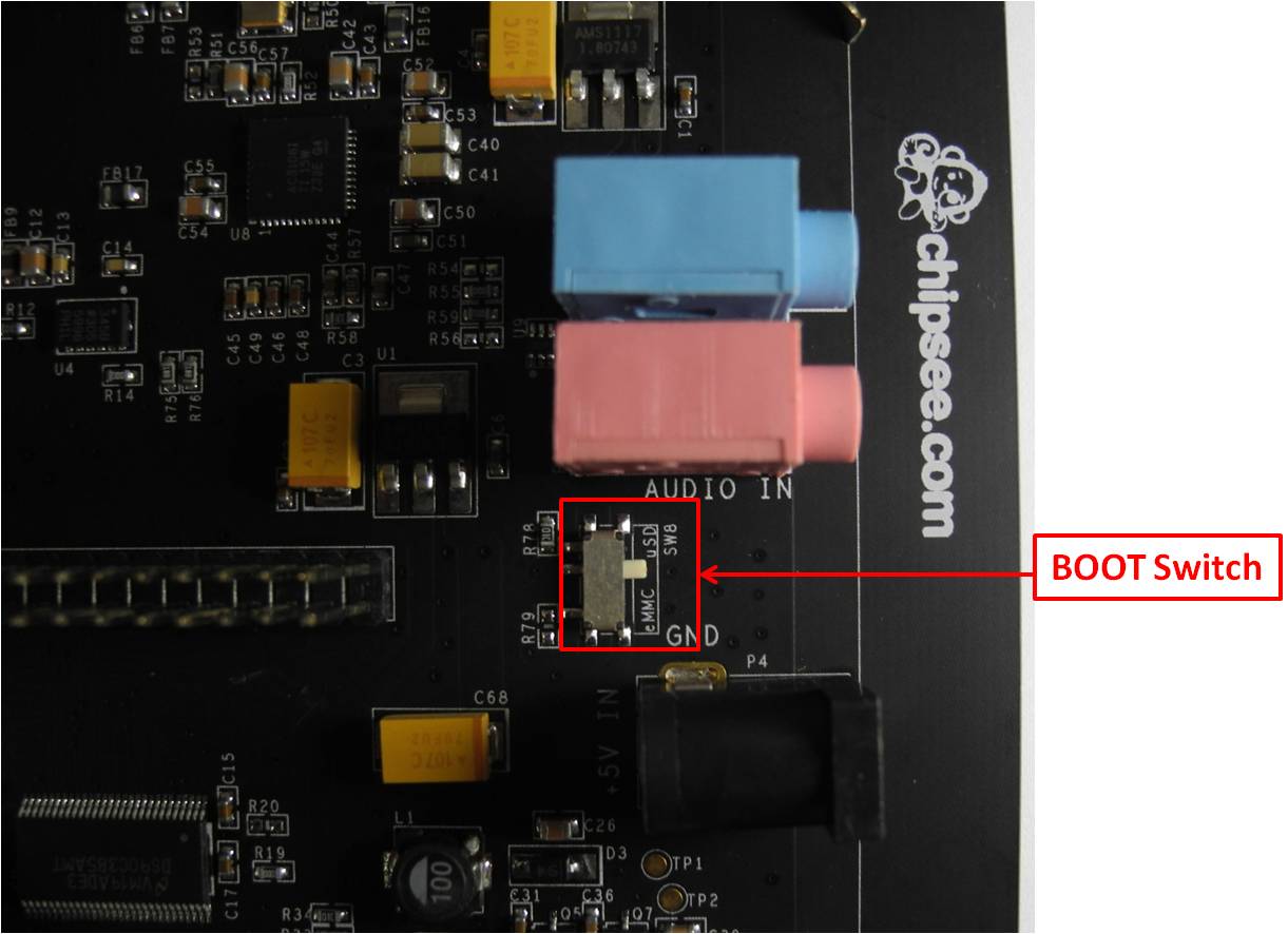
Figure 5
Power and Reset Button
BeagleBone Black use Button S3 as Power button, BBB-EXP7H connect this signal to Button SW6 as Figure 6 shows. So BBB-EXP7H button SW6 will have the same effect with S3 on the BeagleBone Black.
BeagleBone Black use Button S1 as Reset button, BBB-EXP7H connect this signal to Button SW7 as Figure 6 shows. So BBB-EXP7H button SW7 will have the same effect with S1 on the BeagleBone Black.
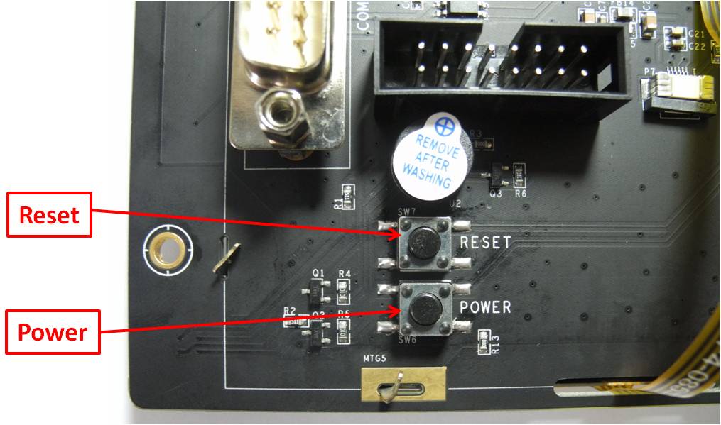
Figure 6
User Keys and user LED
BBB-EXP7H have add 5 user keys as SW1 to SW5 as Figure 7 shows, User can define the key function in software, ChipSee have define it in Android as:
HOME
BACK
MENU
VOLUME UP
VOLUME DOWN
BBB-EXP7H add two user LEDs as Figure 7 shows. User can define its function in software.
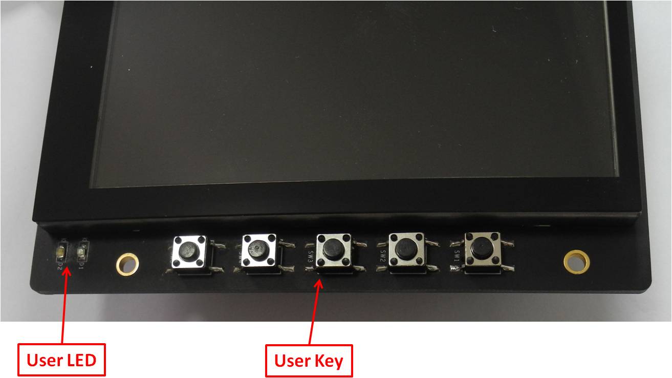
Figure 7
Audio Input and Output
BBB-EXP7H has audio input and output as Figure 8 shows. The expansion board use standard 3.5mm connector. Blue Connector P8 is output, Pink Connect P9 is input.
User can connect the output to any other speaker. As for the Input, it’s “MIC in”, NOT “Line In”, that means user can connect Microphone to the connector directly.
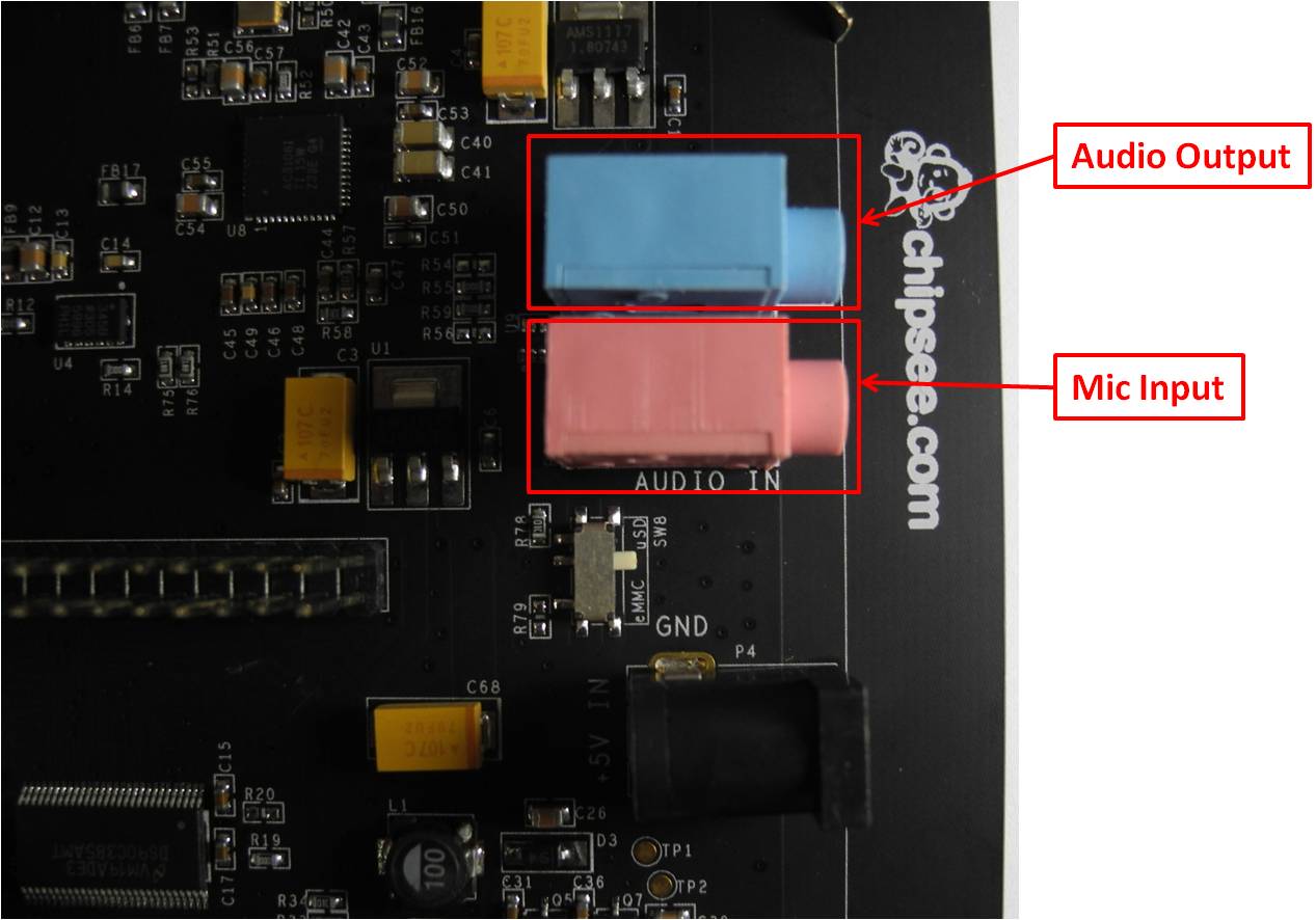
Figure 8
About RTC
BBB-EXP7H adds RTC support, and adds Lithium Battery CR1220 to keep the time as Figure 9 shows. That means the system time will not lost when power off. Be attention the Battery CR1220 is NOT Mount on by default because of International shipment Limitation. User should purchase this Lithium battery and mount on by themselves.
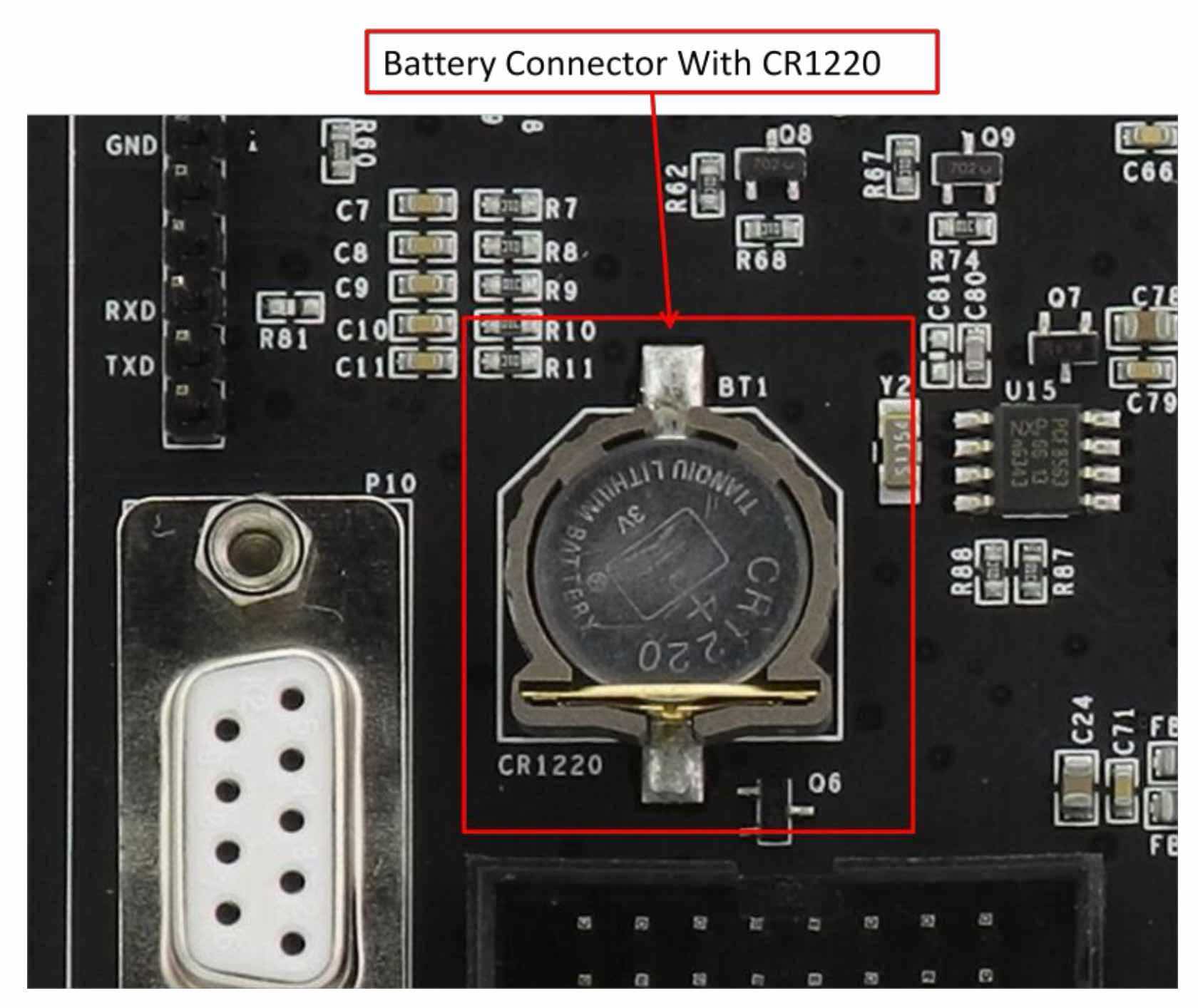
Figure 9
About the RS232 , RS485 and CAN on Expansion board
BBB-EXP7H have add RS232 ,RS485, CAN function to the connector P10, P12 and P13 as Figure 2 shows.
DB9 Connector P10 connects to the CPU UART0, It use RS232 Level |
||
|---|---|---|
Pin Number |
Definition |
CPU Function |
2 |
TXD |
UART0, CPU PIN D15 and D16 |
3 |
RXD |
|
5 |
GND |
|
1,4,6,7,8,9 |
Not Connected |
|
P13 connects to the CPU UART0, But It use 3.3V TTL Level. |
||
|---|---|---|
Pin Number |
Definition |
CPU Function |
1 |
GND |
|
4 |
RXD |
|
5 |
TXD |
UART0, CPU PIN D15 and D16 |
2,3,6 |
Not Connected |
|
P12 Definition |
||
|---|---|---|
Pin Number |
Definition |
CPU Function |
1 |
GND |
|
2 |
CAN0_L |
DCAN0, CPU PIN D17 and D18 |
3 |
CAN0_H |
|
4 |
RS485_2+ |
UART4, CPU PIN T17 and U17 |
5 |
RS485_2- |
|
6 |
RS485_1+ |
UART2, CPU PIN A15 and B17 |
7 |
RS485_1- |
|
8 |
RS232_0_TXD |
UART0, CPU PIN D15 and D16 |
9 |
RS232_0_RXD |
|
10 |
RS232_1_TXD |
UART1, CPU PIN D15 and D16 |
11 |
RS232_1_RXD |
|
12 |
+5V |
|
Be Attention:
COM0 signal have been connect out from Beaglebone Black for customer to debug. This product connect COM0 to P13 directly, it use 3.3V TTL logic. And it product also change the COM0 signal to RS232 level at the same time, then connect the RS232 signal to P10 and P11. Be Attention, The COM0 RXD signal connect to RS232 Level circuit by default, and not connect to P13. That means if you monitor COM0 debug signal from P13, you can receive message from the system, but you can’t input any message to the system. If you want to use P13 to input signal to system, please remove R60, and solder the R81 with 0 Ohm 0603 package resistor,As Figure 10 shows:
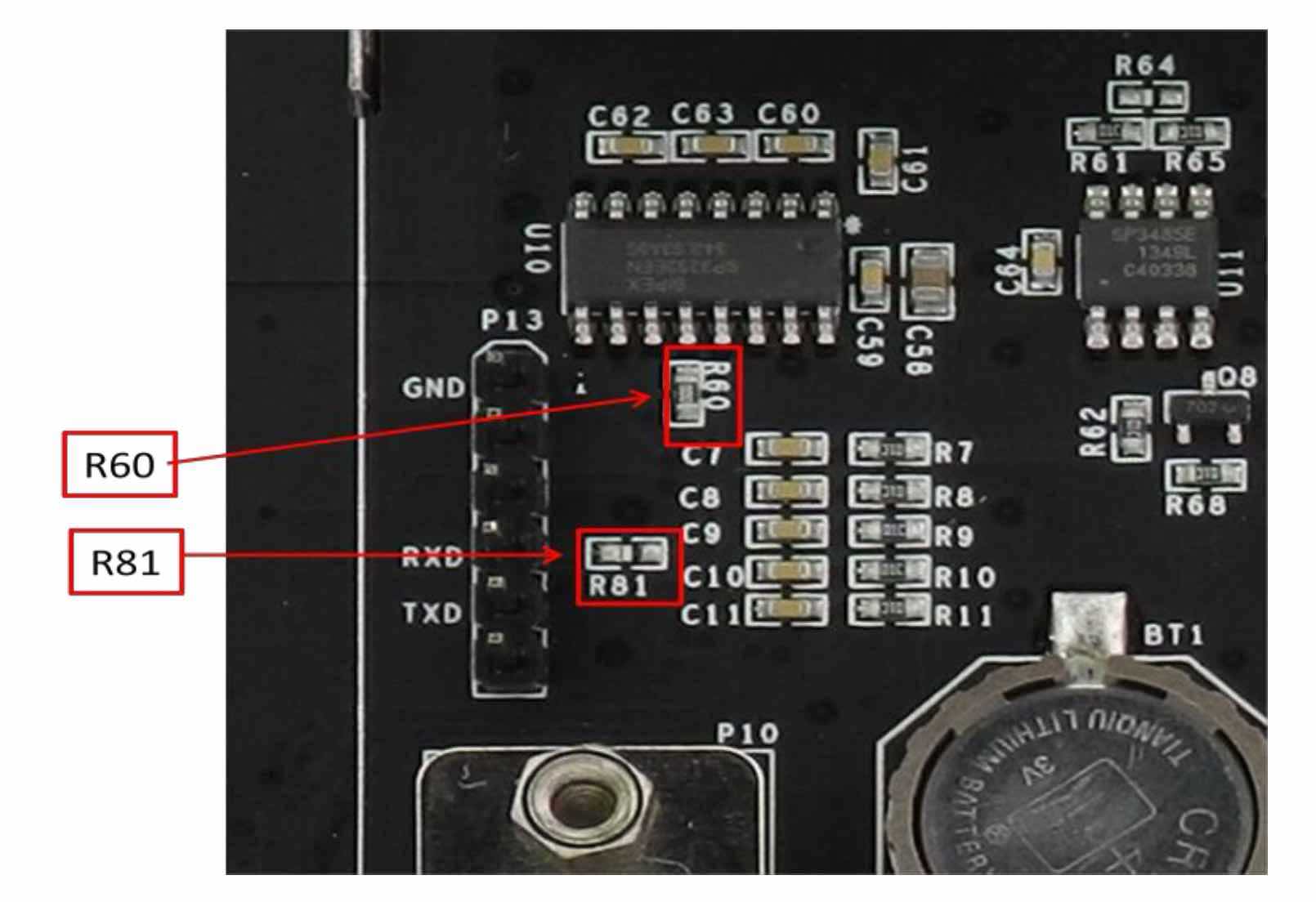
Figure 10
The RS232_0 signals have been connect to the DB9 connector P10 and connector P12 Pin8 and Pin9 at the same time. They are totally the same. As for this function, you can use one connector one time.
Mechanical Dimension
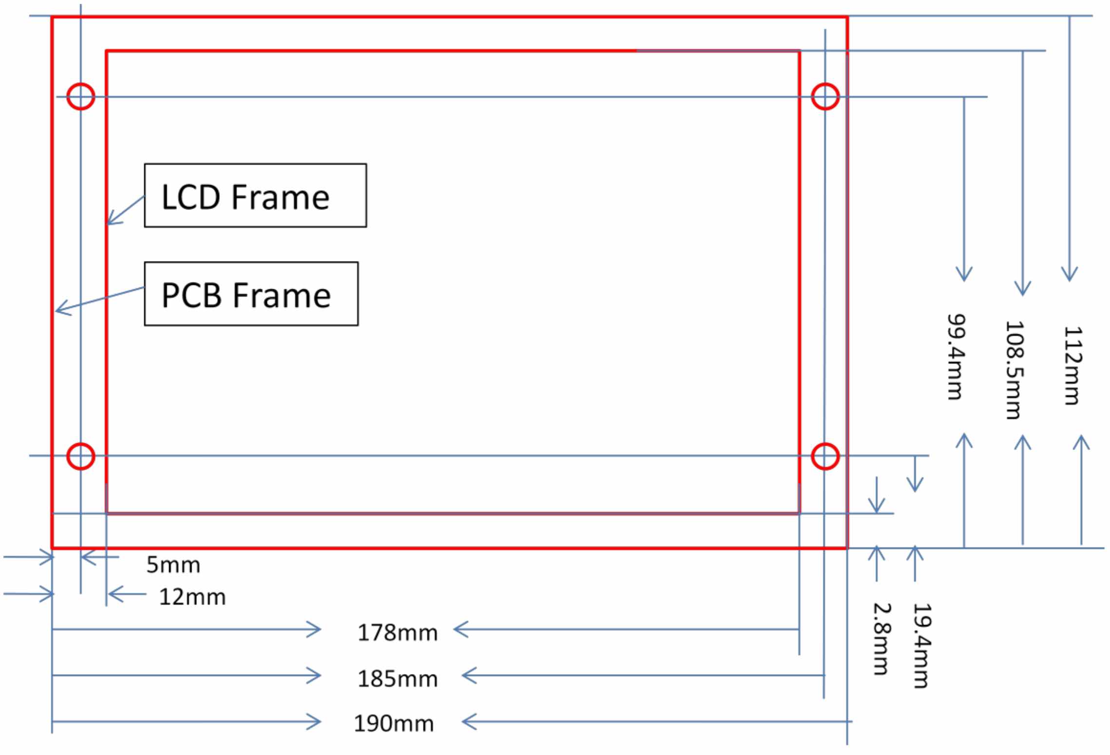
Figure 11
Product Video
Android 4.1 http://youtu.be/FebYqMws0g4
WindowsCE 6.0 http://youtu.be/S2Ttujf6cWU
Disclaimer
This document is provided strictly for informational purposes. Its contents are subject to change without notice. Chipsee assumes no responsibility for any errors that may occur in this document. Furthermore, Chipsee reserves the right to alter the hardware, software, and/or specifications set forth herein at any time without prior notice and undertakes no obligation to update the information contained in this document.
While every effort has been made to ensure the accuracy of the information contained herein, this document is not guaranteed to be error-free. Further, it does not offer any warranties or conditions, whether expressed orally or implied in law, including implied warranties and conditions of merchantability or fitness for a particular purpose. We specifically disclaim any liability with respect to this document, and no contractual obligations are formed either directly or indirectly by this document.
Despite our best efforts to maintain the accuracy of the information in this document, we assume no responsibility for errors or omissions, nor for damages resulting from the use of the information herein. Please note that Chipsee products are not authorized for use as critical components in life support devices or systems.
Technical Support
If you encounter any difficulties or have questions related to this document, we encourage you to refer to our other documentation for potential solutions. If you cannot find the solution you’re looking for, feel free to contact us. Please email Chipsee Technical Support at support@chipsee.com, providing all relevant information. We value your queries and suggestions and are committed to providing you with the assistance you require.