PPC-J1900-101-C
Version 2.0


Product Overview
The PPC-J1900 series PPC-J1900-101-C is a rugged, high-quality NEMA/IP65-compliant industrial panel PC. This single board computer features a 10.1” multi-point capacitive touch screen with a resolution of 1280 x 800 pixels.
The PPC-J1900-101-C Industrial Panel PC is powered by Intel® Celeron® J1900 quad-core CPU and equipped with a broad range of connectivity options, allowing it to meet highly demanding application requirements in harsh industrial or outdoor environments.
A specially designed magnesium-aluminum alloy housing with fins for increased heat dissipation serves as a passive cooler, eliminating the need for built-in fans. The fan-less design reduces noise, as well as the maintenance costs and efforts, increasing reliability at the same time.
Caution
Be careful when handling the product while it is operating: the back panel might become hot under heavy CPU load.
Product Changes
Ver 2.0
Released on Jul 1, 2025
Warning
Breaking Changes: this product is completely redesigned.
If you bought PPC-J1900-101-C before July 1, 2025, please note the new board (ver 2.0) is not compatible with the previous board (ver 1.1).
Ver 1.1
Initial Release
Ordering Options
Most of the Chipsee products can be customized during the ordering process. The product will be shipped with the pre-installed factory defaults if no extra requirements are specified. The table in the Hardware Features section provides information about the default options bundled with the product.
Note
You can order PPC-J1900-101-C from the official Chipsee Store or from your nearest distributor.
Operating System
By default, PPC-J1900-101-C comes with the Ubuntu Linux operating system (OS) pre-installed. A different OS can be selected during the ordering process.
In addition to Linux, PPC-J1900-101-C also supports Windows 7, Windows 8 and Windows 10.
Optional Features
The PPC-J1900-101-C Industrial Panel PC does not include WiFi/BT and/or 3G/4G modules by default. The Wi-Fi/BT module is optional and can be selected during the ordering process.
The 3G/4G module is a mini-PCIe module, WiFi/BT module is also a mini-PCIe module. There is only 1 mini-PCIe socket on the board, so only one (4G or WiFi) module can be installed. You may use a USB module together with the mini-PCIe module if you need both 4G and WiFi, though.
Warning
Hardware Features
The PPC-J1900-101-C Industrial Panel PC offers a broad range of performance and connectivity options for scalable integration, providing expandability according to future needs.
Some of the key features are listed in the table below.
PPC-J1900-101-C |
|
|---|---|
CPU |
Intel® Celeron® J1900, 2GHz, Quad-Core, 2MB Cache, TDP=10W |
GPU |
Intel® HD integrated GPU, 512MB shared memory |
RAM |
Default 4GB, maximum 8GB, DDR3L 1333 SO-DIMM |
Display |
10.1” LCD, resolution 1280 x 800 px, brightness 350 cd/m2 |
Storage |
Default mSATA 128GB SSD, supports 256/512GB |
Touch |
Capacitive Touch Screen |
USB |
2 x USB 3.0 HOST, 2 x USB 2.0 HOST ports (Type A) |
LAN |
1 x RJ45, 1 Gbps Ethernet Controller |
UART |
5 x RS232, 1 x RS485 |
GPIO |
N/A |
3G/4G |
Optional, module available from other manufacturers/stores |
WiFi/BT |
Optional, module available from the Chipsee store |
HDMI |
N/A |
VGA |
1 x VGA out |
mini-PCIe |
1 x mini PCIe |
Power IN |
12V DC |
Power Consumption |
17W |
OS |
Ubuntu Linux (default), Windows 7 / 8 / 10 (optional) |
Operating Temp. |
From -15°C to 60°C (no condensation) |
Storage Temp. |
From -20 °C to 70°C (no condensation) |
Dimensions |
253.20 X 171.83 X 35mm |
Mounting |
VESA 100, Panel mounting with fixtures |
Weight |
1200g |
Power Input
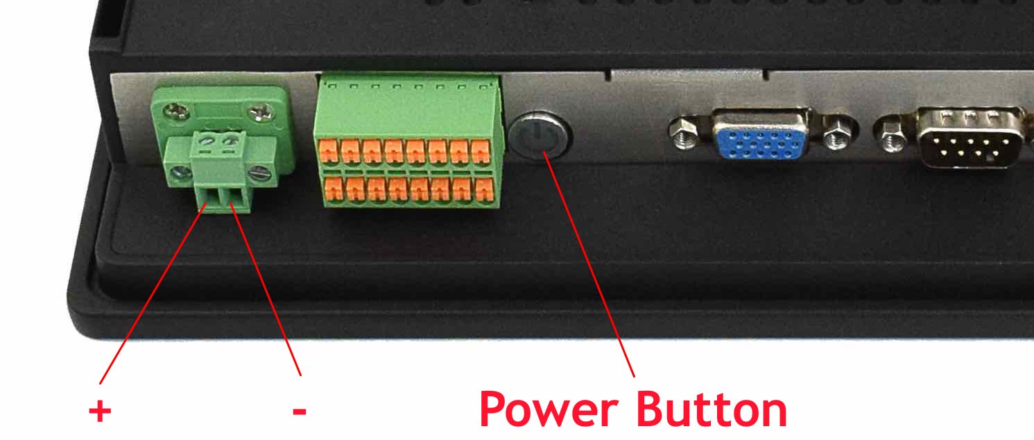
The PPC-J1900-101-C Industrial Panel PC can be powered by 12V DC power supply. The power input connector is a 2-pin, 3.81mm screw terminal.
The POWER button can be used to switch the power ON or OFF.
Check the image below for positive and negative DC input, you can use either pair of the two ports:
12V DC Power Input
Note
If the product is used to control some key processes, it is highly recommended to use an Uninterruptible Power Supply (UPS) to prevent critical data loss.
Touch Screen
PPC-J1900-101-C is equipped with a multi-point capacitive touch screen. Its multitouch detection capability enables implementation of some advanced GUI operations, such as two-finger zoom or rotation.
The capacitive touch screen can be operated by fingers, gloves with a special coating, or a conductive stylus.
Size/Type: 10.1” multi-point capacitive touch screen
Touch screen structure: G+F+F
Surface Strength: 7H
Surface Hardness: 50G steel ball 70cm impact drop 3 times not broken
Service Life (MTBF): 50 million touch events
Light Transmittance: > 92%
Connectivity
There are many connectivity options available on the PPC-J1900-101-C industrial PC. It has 4 x USB Type A connectors configured as HOSTS, 1 x VGA out port, 1 x RJ45 supporting Gigabit Ethernet (GbE), and 5 x RS232, 1 x RS485 connectors.
RS232/RS485
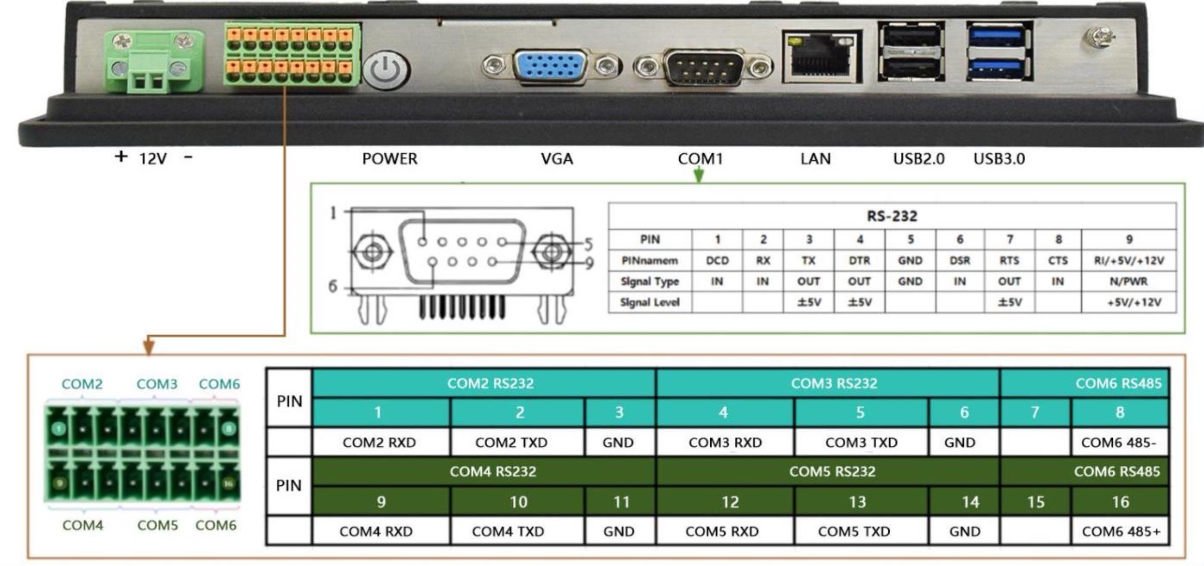
The PPC-J1900-101-C Industrial Panel PC has 1 x 9-pin D-sub connectors and 1 x 16-pin 3.81mm connector with pluggable terminal block. The 9-pin D-sub connector labeled as COM1 is RS232.
COM 2/3/4/5 are RS232 and COM6 is RS485:
RS232 / RS485 Interfaces
USB HOST
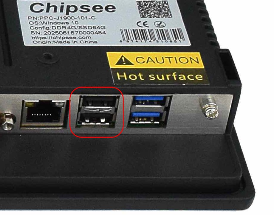
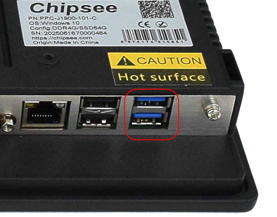
PPC-J1900-101-C is equipped with 2 x USB 2.0 connectors and 2 x USB 3.0 HOST connectors.
USB 2.0 HOST Port
USB 3.0 HOST Port
Warning
Be careful not to touch surrounding electronic components accidentally while plugging USB devices into the embedded IPC version.
LAN
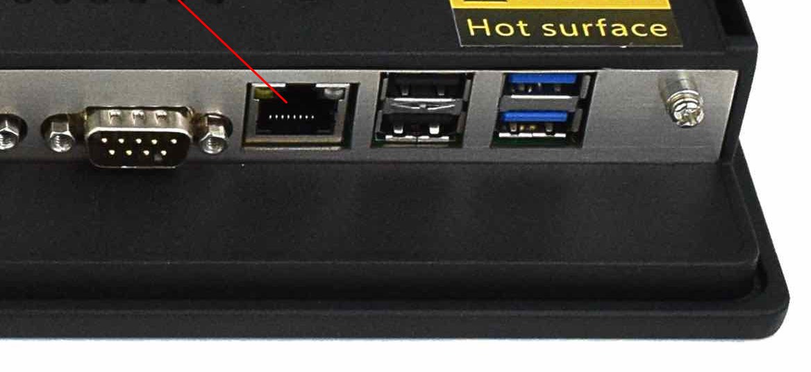
1 x LAN (RJ45) provide Ethernet connectivity over standardized Ethernet cables. The integrated two-port Ethernet interface supports 10/100/1000BASE-T/TX specifications with automatic speed negotiation and Wake on LAN (WoL) functionality.
Power over Ethernet (PoE) is not supported.
LAN/RJ45
Note
Use CAT5 or better cables to achieve full data throughput over maximum distance defined by the 1000BASE-T standard (100m).
VGA
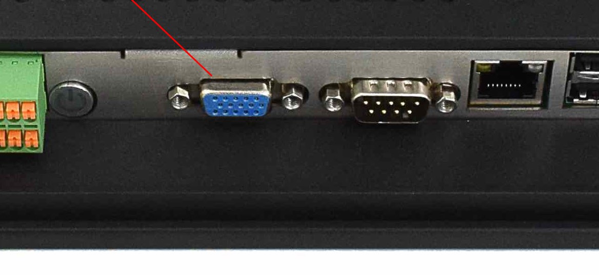
The PPC-J1900-101-C Industrial Panel PC is equipped with 1 x VGA connector as video output. The VGA connector allows connecting an additional (external) monitor. VGA output resolution can be configured by the software.
HDMI Connector
Mounting Procedure
The PPC-J1900-101-C Industrial Panel PC supports VESA 100 x 100 mounting pattern with 4 x M4 screws, enabling simplified installation onto any standard VESA mounting rack. Other mounting options might also be supported according to the table in the Hardware Features section.
You can find detailed information about mounting in the Mount IPC Guide.
Mechanical Specifications
The outer mechanical dimensions of The PPC-J1900-101-C Industrial Panel PC are 253.20 X 171.83 X 35mm (W x L x H). Please refer to the technical drawing in the figure below for details related to the specific product measurements.

Figure 854: PPC-J1900-101-C Technical Drawing
Disclaimer
This document is provided strictly for informational purposes. Its contents are subject to change without notice. Chipsee assumes no responsibility for any errors that may occur in this document. Furthermore, Chipsee reserves the right to alter the hardware, software, and/or specifications set forth herein at any time without prior notice and undertakes no obligation to update the information contained in this document.
While every effort has been made to ensure the accuracy of the information contained herein, this document is not guaranteed to be error-free. Further, it does not offer any warranties or conditions, whether expressed orally or implied in law, including implied warranties and conditions of merchantability or fitness for a particular purpose. We specifically disclaim any liability with respect to this document, and no contractual obligations are formed either directly or indirectly by this document.
Despite our best efforts to maintain the accuracy of the information in this document, we assume no responsibility for errors or omissions, nor for damages resulting from the use of the information herein. Please note that Chipsee products are not authorized for use as critical components in life support devices or systems.
Technical Support
If you encounter any difficulties or have questions related to this document, we encourage you to refer to our other documentation for potential solutions. If you cannot find the solution you’re looking for, feel free to contact us. Please email Chipsee Technical Support at support@chipsee.com, providing all relevant information. We value your queries and suggestions and are committed to providing you with the assistance you require.
